Write a blog post explaining the role of FACTS in enhancing the stability and reliability of electrical grids. Describe the various FACTS devices, including Static Var Compensation (SVC) Thyristor Controlled Series Compensatoes (CSC), Stanc Phase Shifters (SPS), Static Condensers (STATCON), Static Synchronous Series Compensators (SSSC), and Unified Power Flow Commlers (UPFC) Descuss how these devices contribute to grid optimization and power quality.
Static Var Compensation (SVC)
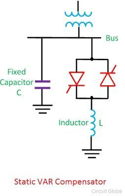
A static VAR compensator is a parallel combination of controlled reactor and fixed shunt capacitor shown in the figure below. The thyristor switch assembly in the SVC controls the reactor. The firing angle of the thyristor controls the voltage across the inductor and thus the current flowing through the inductor. In this way, the reactive power draw by the inductor can be controlled.
The SVC is capable of step less adjustment of reactive power over an unlimited range without any time delay. It improves the system stability and system power factor. Most commonly used SVC scheme are as follows.
- Thyristor controlled reactor (TCR)
- Thyristor-switched capacitor (TSC)
- Self Reactor (SR)
- Thyristor controlled reactor – Fixed capacitor (TCR-FC)
- Thyristor-switched capacitor – Thyristor controlled reactor (TSC-TCR)
Advantage of Static VAR Compensator
- It increased the power transmission capability of the transmission lines.
- It improved the transient stability of the system.
- It controlled the steady state and temporary over voltages.
- It improved the load power factor, and therefore, reduced line losses and improved system capability.
Static VAR compensator has no rotating parts and is employed for surge impedance compensation and compensation by sectionalizing a long transmission line.
Thyristor Controlled Series Compensation(TCSC)
Unified Power Flow Controller (UPFC)
1. Principle of Operation
Ø The UPFC is the most versatile FACTS controller developed so far, with all encompassing capabilities of voltage regulation, series compensation, and phase shifting.
Ø It can independently and very rapidly control both real- and reactive power flows in a transmission.
Ø It is configured as shown in Fig. and comprises two VSCs coupled through a common dc terminal.


Comments
Post a Comment